Post by aaron_do on Dec 13th, 2007, 7:24pm
Hi all,
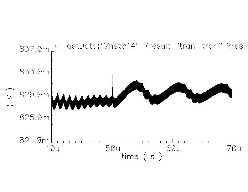
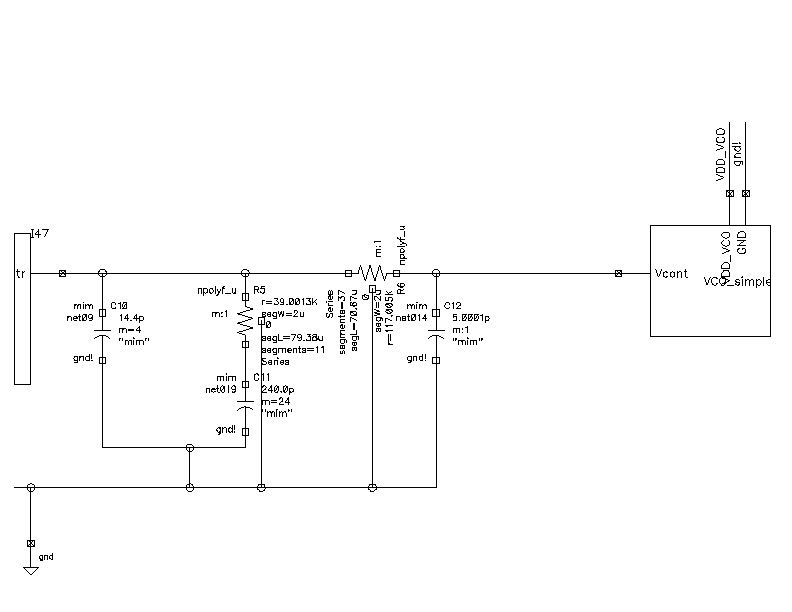
here's a plot of the control voltage of the PLL, and the loop filter. The last cap on the loop filter was increased from 4p to 5p to see if there would be any change. Also, in this simulation, the PLL was simulated for 50 us before applying the change in tank capacitance of the VCO, so the control voltage is not quite as settled as it would be after 60 us. Any thoughts on why I am getting this ripple are welcome. Plots of the divider output and the reference frequency suggest that the PLL has not left the locked condition.
thanks,
Aaron