The Designer's Guide Community Forum
https://designers-guide.org/forum/YaBB.pl
Design >> Analog Design >> low-voltage pseudo differential amplifier CMFB problem
https://designers-guide.org/forum/YaBB.pl?num=1234504715

Message started by aaron_do on Feb 12th, 2009, 9:58pm

Title: low-voltage pseudo differential amplifier CMFB problem
Post by aaron_do on Feb 12th, 2009, 9:58pm

Hi all,


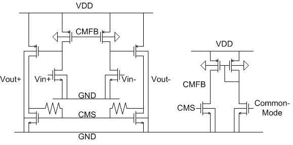
i'm trying to design a low-voltage pseudo-differential amplifier. There are no tail currents. It seems that no matter what i do, I cannot stop the CM oscillation. At the desired operating point, the phase margin is well above 60 degrees, but i suspect that the circuit is simply too sensitive to CM disturbance. I found that if I use CMFB without trying to define the CM voltage, then it works ok. However, in that case it is very susceptible to variation due to process variation. Does anybody have any experience in this matter, and care to give some feedback?


thanks,
Aaron

Here's the schematic. Common-mode is the voltage i want to set the CM level to.


Title: Re: low-voltage pseudo differential amplifier CMFB problem
Post by thechopper on Feb 15th, 2009, 6:34pm

Hi Aaron,

It looks to me from your schematic that you cannot force the output common mode voltage:

The output common mode will be given by the gate - source voltage CMS and it cannot be any other value. That aligns with the fact you see the circuit is well-behaved when you do not force the output common mode.
Trying to force the output common mode would force common mode current to flow through the resistors connected at CMS, but such current has nowhere to go. So you cannot move the "natural" common mode of this circuit.
I might be missing something here but that is my impression.

Regards
Tosei

Title: Re: low-voltage pseudo differential amplifier CMFB problem
Post by aaron_do on Feb 15th, 2009, 9:42pm

Thanks for the reply,


The output CM voltage is determined by the current through the output stage (at CM the load is diode connected), which is controlled by the CMFB. I can't see a problem there. Actually I can get this circuit to work without any problems if the supply voltage is higher and i use a tail current at the input stage.

Based on phase margin analysis of the feedback loops, there should be no problems. I've tried a few variations of this circuit and they all seem to have stability problems.

thanks,
Aaron

Title: Re: low-voltage pseudo differential amplifier CMFB problem
Post by subgold on Feb 16th, 2009, 1:58am

hi aaron,

i doubt a phase margin analysis on the desired operating point is sufficient for CMFB design, because the CMFB should also be able to regulate the circuit even when the operating points are much deviated from the desired values.

Anyway, could you please explain how you get this phase margin? You have three cascading gain stages in the CMFB loop without any compensation, a value well above 60 degrees seems too good to be true.

regards
subgold

Title: Re: low-voltage pseudo differential amplifier CMFB problem
Post by aaron_do on Feb 16th, 2009, 4:13am

Hi subgold,


I think i've found out why it was oscillating (managed to get it to stop), and i'll see if i can post it after I analyze it to make sure. As for the analysis, I broke the loop with an iprobe and ran an stb analysis.

I realize with three gain stages I should have three poles and therefore a poor phase margin, but I guess due to the sizing of the stages, the PM didn't need compensation.

You mentioned that the CMFB should be able to regulate the circuit even when the operating points are deviated from the desired values. I was wondering about that too since I usually only ensure good PM at the operating point (my circuits input and output CM are fixed). However, on start-up, the PM is probably very different from what it is at the desired operating point. So how do we normally deal with this?


thanks,
Aaron

Title: Re: low-voltage pseudo differential amplifier CMFB problem
Post by subgold on Feb 18th, 2009, 4:19am

hi aaron,

have you found the cause of the oscillation?


aaron_do wrote on Feb 16th, 2009, 4:13am:
You mentioned that the CMFB should be able to regulate the circuit even when the operating points are deviated from the desired values. I was wondering about that too since I usually only ensure good PM at the operating point (my circuits input and output CM are fixed). However, on start-up, the PM is probably very different from what it is at the desired operating point. So how do we normally deal with this?


transient simulations with different initial conditions or steps on the CM level seem to be a way to verify, but that is only my experience.

The Designer's Guide Community Forum » Powered by YaBB 2.2.2!
YaBB © 2000-2008. All Rights Reserved.