The Designer's Guide Community Forum
https://designers-guide.org/forum/YaBB.pl
Design >> Analog Design >> Converting differential voltage to digital
https://designers-guide.org/forum/YaBB.pl?num=1327455370

Message started by mixed_signal on Jan 24th, 2012, 5:36pm

Title: Converting differential voltage to digital
Post by mixed_signal on Jan 24th, 2012, 5:36pm

Hi,

I have to digitise a differential O/P of a subcircuit  using dual slope A/D converter.  But my dual slope A/D converter i am designing is single ended. How can I convert differential O/P  to single ended?


Title: Re: Converting differential voltage to digital
Post by raja.cedt on Jan 25th, 2012, 3:02am

hello,
so you have differential signal and you want single ended, so why don't you simply take one signal out differential signal, because differential means you have v and -v...you need single ended means 2*v, so take one signal and use if you want exact differential just amplify by 2.

Title: Re: Converting differential voltage to digital
Post by RobG on Jan 25th, 2012, 5:29pm

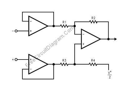
Raja - that might work but you would get the common mode noise including DC. The normal way to do it is to use an instrumentation amplifier like this:


If you can drive resistance you don't need the two buffers up front.

There are many variations that might fit the OP's needs.

Title: Re: Converting differential voltage to digital
Post by mixed_signal on Jan 25th, 2012, 8:15pm

Hi,
I apologise for my mistake. The signal is not absolute differential with V+ and V- but v1 and v2 and both are >0. I want to digitise v1-v2 which is the o/p of a temperature sensor and i dont want to introduce any nonlinearity. In fact they are Vbe1 and Vbe2 of two BJTs.

NB. I dont want to change the sensor core and modify like a bandgap ref to extract Vbe1 - Vbe2.

Title: Re: Converting differential voltage to digital
Post by Dan Clement on Jan 26th, 2012, 4:57am

The typical thing to do is to gain this pat signal up and use a sigma delta ADC. You will need an accurate voltage reference regardless of what type of ADC you use.

What kind of accuracy and resolution are you designing for?


Title: Re: Converting differential voltage to digital
Post by loose-electron on Jan 26th, 2012, 8:02pm

I agree with Dan, the dual slope converter is pretty out of date
and has been replaced by more reliable methods like
sigma-delta converters.

To deal with the conversion, considering its a
sampled time system, there are switched capacitor methods that
work well and do not consume much power.

Title: Re: Converting differential voltage to digital
Post by RobG on Jan 27th, 2012, 2:41pm

Just use a fully differential system and this will be pretty easy. An incremental is just a Delta-Sigma that is reset before each conversion and may work a little better for your app:
click here

If can oversample the signal by a lot then use the simple circuit in the second paper (1987, 16-bits).

Title: Re: Converting differential voltage to digital
Post by raja.cedt on Jan 29th, 2012, 4:12am

hello robg,
small correction in your previous post schematic, why again v+/2 at the end of r4. I guess it's mistake.

Thanks,
Raj.

Title: Re: Converting differential voltage to digital
Post by mixed_signal on Jan 29th, 2012, 8:46am

Hi Dan clement,

I am designig for an uncalibrated inaccuracy of 1C and a resolution of 0.1C with an on current of just 3uA (sensor core+ADC). I know its difficult but thats my goal. The two hard constraints are uncalibrated inaccuracy and low power.

If I use sigma delta  and chopper circuits to minimise the offsets (for uncalibrated inaccuracy) then the power increase. One good thing is that my sensing range is small -20 to 30C and I have a low sampling rate of 1 sample per  minute.

Thanks


Title: Re: Converting differential voltage to digital
Post by RobG on Jan 29th, 2012, 9:38am


raja.cedt wrote on Jan 29th, 2012, 4:12am:
hello robg,
small correction in your previous post schematic, why again v+/2 at the end of r4. I guess it's mistake.

Thanks,
Raj.


I didn't see that, but presumably it is a reference voltage (not the input voltage) chosen so that it will shift the common mode of the output to mid reference. The classical circuit I've seen ahs that voltage tied to ground and R2=R3, R2=R4. Then Vout = R4/R3*(Vin+-Vin-)

Title: Re: Converting differential voltage to digital
Post by RobG on Jan 29th, 2012, 9:59am


mixed_signal wrote on Jan 29th, 2012, 8:46am:
If I use sigma delta  and chopper circuits to minimise the offsets (for uncalibrated inaccuracy) then the power increase. One good thing is that my sensing range is small -20 to 30C and I have a low sampling rate of 1 sample per  minute.


A Delta-Sigma or incremental is going to use FAR less power than a dual slope and more robust. As Jerry said, nobody uses dual slopes anymore. I doubt if you could even meet 10x that power with a dual slope -- MAYBE if you use an external capacitor, and you can't get away with a cheap capacitor on a dual slope.

I mentioned an incremental ADC. If you are continuously sampling the same input a delta-sigma is fine too, except every once it will give you an answer 1lsb different. With an single order incremental the decode is just a counter and you have so much time that you could get 16 bits with a 1kHz clock.

These are the types of circuits I love to design ;)))

Do some searching on google scholar. It wouldn't surprise me if there is a published sensor design to meet your needs.

Title: Re: Converting differential voltage to digital
Post by loose-electron on Jan 29th, 2012, 1:59pm

The temp sensors that get used in microprocessors use the differential current and different size diodes to do this.

Google search on microprocessor temperature and fan control systems, there was a bunch of stuff on this around 1998 give or take a few years.
(I designed one while I as at Fairchild then.)

Consider doing either sigma-delta or VCO counter architecture, which is not as well published.

Title: Re: Converting differential voltage to digital
Post by mixed_signal on Jan 30th, 2012, 8:13am

Thanks everyone for your valuable suggestions!

Title: Re: Converting differential voltage to digital
Post by loose-electron on Jan 30th, 2012, 9:19am

UPDATE - Never mind, I saw your earlier references- thanks!

"Incremental" ADC?

What does that term mean Rob?


RobG wrote on Jan 29th, 2012, 9:59am:
[quote author=mixed_signal link=1327455370/0#8 date=1327855567]
I mentioned an incremental ADC.


Title: Re: Converting differential voltage to digital
Post by RobG on Feb 1st, 2012, 12:43pm

Incremental ADC is basically a delta-sigma except that it is reset before each conversion. This allows it to be used for multi-channel high resolution ADCs since the current result doesn't depend on the past results. Also good for single-event upset environments for the same reason. The decimation filters are easier - for a first order it is just a counter, but you need a higher OSR than a delta-sigma.

edit - I just saw that you saw my references  ;D

Title: Re: Converting differential voltage to digital
Post by mixed_signal on Feb 1st, 2012, 6:53pm

Hi,

I am designing a smart temperature sensor with following specs:
1. On current 3uA (sensor+ADC)
2. Inaccuracy with no calibration 1C
3. Resolution 0.1c
4. Range -20C to 30C
5. Sampling rate 1 sample/minute. (too slow!!)

I am using bipolar core. I have the following questions:


1. What is the typical value of the bias current of the BJTs? i have power constraint. So planning to use 100nA.

2. Two BJTs can be kept at different current densities by different current ratio or emitter area ratio? Why in temperature sensors usually current ratio is preferred and emitter area is kept constant.

3.  What type of opamp is best suitable for bandgaps/ temp sensors?
What is the typical gain, UGB etc. of the op amp? May I use opamp in subthreshold? Moreover, the op amp offset causes lot of inaccuracy. So, I need to use auto zero or chopper. It also should have high PSRR.


Thanks! :)

Title: Re: Converting differential voltage to digital
Post by loose-electron on Feb 1st, 2012, 9:26pm

the current density thing is due to the math involved.

I did one of these about 10 years ago, and if you do differential current of different junction sizes a lot of the process varaibles fall out of the equation making the math simpler and less process dependent.

search the literatuire for stuff on temp sensors using PN diode junctions. Thees a bunch of publications in the area.

Title: Re: Converting differential voltage to digital
Post by mixed_signal on Feb 2nd, 2012, 7:05am

Thank you loose electron!

Title: Re: Converting differential voltage to digital
Post by RobG on Feb 2nd, 2012, 10:29am


mixed_signal wrote on Feb 1st, 2012, 6:53pm:
Hi,

I am designing a smart temperature sensor with following specs:
1. On current 3uA (sensor+ADC)
2. Inaccuracy with no calibration 1C
3. Resolution 0.1c
4. Range -20C to 30C
5. Sampling rate 1 sample/minute. (too slow!!)

I assume that you have a bandgap reference provided. The bandgap value will likely be the largest source of the error so hopefully for you it is someone else's issue.


Quote:
1. What is the typical value of the bias current of the BJTs? i have power constraint. So planning to use 100nA.

It depends on the BJT area so you'll want to use a pretty small device - ~2x2 um^2. As I hope you know, if you operate two bipolars at two different current densities (say the ratio is M) then the difference between the emitters is kT/q*ln(M). That has no process dependence so you'll be in great shape.

Except that is only true at a proper bias.

To make sure you are in a good operating region, sweep the current and measure the voltage difference and note where it falls off at the high current and low current. Obviously you want to operate somewhere in the middle. Try this at hot/cold

Mismatch of your mirrors will have to be managed. BJTs match very well.


Quote:
2. Two BJTs can be kept at different current densities by different current ratio or emitter area ratio? Why in temperature sensors usually current ratio is preferred and emitter area is kept constant.

Probably because that is how the guy before did it. I don't think there is any inherent advantage, but the bipolars can be relatively large so it can save area. You can also double sample the same BJT at two difference current densities to get the delta Vbe using only one BJT and a two value current source. I should have charged you for that one, but I won't tell you how to do it w/ a single current source   ;)

If you can do it, put "N" BJTs in series or in Darlington configuration so that your differential voltage is N*kT/q*ln(M) instead of using an opamp to gain up the kT/q*ln(M) signal. Guess I'm in a "give it away" mood today.

Quote:
3.  What type of opamp is best suitable for bandgaps/ temp sensors?
What is the typical gain, UGB etc. of the op amp? May I use opamp in subthreshold? Moreover, the op amp offset causes lot of inaccuracy. So, I need to use auto zero or chopper. It also should have high PSRR.

You'll want the lowest noise/highest gain possible, which is IMO a two stage Miller type opamp (except compensate it by putting the compensation between the gate/source of the output device for good AC PSRR).

Chop it. Barrel shift your mirror elements if they give you issues. Use as much current as you need and shut it down for 59 seconds. There, I just cut your power by a factor of 60 and solved your mismatch problems.   :) If you give me a VPN account and some money I can probably do it for 300nA on average.   :o

Title: Re: Converting differential voltage to digital
Post by loose-electron on Feb 2nd, 2012, 2:25pm

Rob - good analysis.

Its been a while, but I seem to remember it was 2 different
currents, on 2 different size junctiuons, and a lot of the
process variables fell out of the equation.

Its in the literature, Intel people did one of the early designs on
this and it went into the Pentium 1 for temp monitor and fan control.

Title: Re: Converting differential voltage to digital
Post by Dan Clement on Feb 2nd, 2012, 6:17pm

Hitting an uncalibrated accuracy spec of one degree is not trivial.

You will have to do chopping of all opamps. You will also have to do dynamic element matching.

Even with all these tricks you may not make it.

If you are in an advanced process the problems only get worse since the bipolar transistor betas drop terribly.

Check out the papers by Pertjis and Makinwa in IEEE JSSC.

Title: Re: Converting differential voltage to digital
Post by Dan Clement on Feb 2nd, 2012, 6:27pm

You also have to be careful if you are only using a current difference into the same unit sized bipolar transistors. The beta curves are a function of current and if your ratio is too large you will have problems.

Also you certainly don't need one second or the measurement. With a first order sigma delta you will only need a few hundred milliseconds. I would recommend a second order if you can handle the more complex decimation filter.

Title: Re: Converting differential voltage to digital
Post by RobG on Feb 2nd, 2012, 6:44pm


Dan Clement wrote on Feb 2nd, 2012, 6:27pm:
Also you certainly don't need one second or the measurement. With a first order sigma delta you will only need a few hundred milliseconds. I would recommend a second order if you can handle the more complex decimation filter.


Dan - if you know a simple way to chop out the offsets from a second order let me know... I'm trying to understand that right now!
rg

Title: Re: Converting differential voltage to digital
Post by Dan Clement on Feb 3rd, 2012, 5:03am

Rob,

If you don't have a solution I'm not hopeful I would have one... :)

The last circuit I did was a second order modulator temp sensor that used charge balancing. This circuit setup is similar to the papers mentioned above by Perrtjiis, Makinwa, and Huijsing (sp?).

In this setup I did CDS for the first integrator.  On phi1 the feedback cap is shorted and the integrator is in unity gain. On phi2 it's reconnected to make it an integrator again. The inputs are swapped every integration cycle. I hope this makes sense, it's early in the AM!

I did not do anything about the offset in the second integrator as its effect is supposed to be attenuated by the open loop gain of the first stage. At least that's what the smart guys like you have figured out.

In the literature mentioned above it is also possible to do nested chopping where at the system level another chop is done but at a very slow frequency.

Not sure if this will help or not...

Have fun!

Title: Re: Converting differential voltage to digital
Post by RobG on Feb 3rd, 2012, 1:02pm

Dan - Don. T was talking at lunch today about some CDS + chopping that Makinwa was doing so that must be the same thing. Quiquempoix (JSSCC july '06) did fractal chopper sequencing, but he has a patent on it >:( .

I started writing equations for the output of the 2nd integrator with 1st stage chopping this morning. I can now see how the offset grows as Nsamp*Vos compared to Nsamp^2*Vin so it should help, but I don't know. I guess you also have to be careful of aliasing things back down.

So that is why I was thinking 1st order with so much time. Then you can chop and all you have to do is add up the result at the end!

rg

Title: Re: Converting differential voltage to digital
Post by loose-electron on Feb 4th, 2012, 11:04am

I know sigma delta is sexy right now but
have you considered a VCO counter approach?

Its simple, and with a differential system most
of the offsets and whatnot cancel each other out.

Title: Re: Converting differential voltage to digital
Post by Dan Clement on Feb 6th, 2012, 5:32am

Jerry,

I have never seen this topology.  Do you have any reference material?  It sounds interesting.

Thanks,
Dan

Title: Re: Converting differential voltage to digital
Post by mixed_signal on Feb 6th, 2012, 8:29am

Thank you all for the valuable information!
I have to design the voltage reference as well for the sensor.

I am using a process where the max voltage Vdd  is 1.2v and the bandgap voltage is slightly <1.14V. Is it advisable to  go for voltage mode band gap reference where I will have vref=1.2v with few mV overdrive for my PMOS.

Will current mode bandgap be a better option? Is it suitable for sensor with uncalibrated accuracy? Since resistors in current mode is large I am wondering about the offsets and the inaccuracy.

Thanks!


Title: Re: Converting differential voltage to digital
Post by loose-electron on Feb 6th, 2012, 9:23pm


Dan Clement wrote on Feb 6th, 2012, 5:32am:
Jerry,

I have never seen this topology.  Do you have any reference material?  It sounds interesting.

Thanks,
Dan


Its really not that well written on because the concept has been around so long.

In concept:

1. Build a VCO that is linear, frequency out is proportional to voltage in..

2. Connect VCO input to a reference voltage.

3. Count number of clock cycles that occur in a fixed time period.

4. Connect VCO to ground.

5. Count number of clock cycles that occur in a fixed time period.

6. Take the difference between the two numbers. (think line slope)

7. Use the DC = 0 value as the offset number.

8. The two numbers represent a conversion line now, you have an AX + B
transfer function.

The linearity of the ADC is a direct function of the linearity of the VCO
transfer. Using an op-amp  V to I converter into a capacitor, some comparators and switches
make for a simple but very linear oscillator.

Absolute value is dependent on the voltage reference.

Pretty simple works well, slow to convert, but capable to get it done.
Be careful of flicker noise, that bit me on one of these --  there
was no flicker in the models used.

Title: Re: Converting differential voltage to digital
Post by Dan Clement on Feb 7th, 2012, 5:08am

Thanks Jerry, that sounds like an efficient topology.

Title: Re: Converting differential voltage to digital
Post by loose-electron on Feb 9th, 2012, 5:01pm


Dan Clement wrote on Feb 7th, 2012, 5:08am:
Thanks Jerry, that sounds like an efficient topology.


Simple, but quite slow...


Title: Re: Converting differential voltage to digital
Post by RobG on Feb 10th, 2012, 6:50am


mixed_signal wrote on Feb 6th, 2012, 8:29am:
Thank you all for the valuable information!
I have to design the voltage reference as well for the sensor.

I am using a process where the max voltage Vdd  is 1.2v and the bandgap voltage is slightly <1.14V. Is it advisable to  go for voltage mode band gap reference where I will have vref=1.2v with few mV overdrive for my PMOS.

Will current mode bandgap be a better option? Is it suitable for sensor with uncalibrated accuracy? Since resistors in current mode is large I am wondering about the offsets and the inaccuracy.


You can not do a traditional bandgap with a 1.2V supply. I'm a tad worried that you are taking on a such a challenging task and not knowing that as there are many more pitfalls that are much more subtle. Anyway, getting the tolerance you need with a current mode bandgap (like Banba) will be tough at the power levels you are dealing with. Watch process corners and mismatch in your current mirrors. There are far better ways to do this than with a full bandgap, but I'm a contractor (and Jerry is too) and bandgaps/temp sensors are a big part of my "mental inventory" so I don't want to give any more hard earned information away for free. Sorry....

Jerry - the 1st order incremental is basically a refined version of the vco-type converter. I remember a paper about temperature to frequency converter that may have used that being published a few years back, so the OP might be able to find it (there I go giving it away again)  :)

Title: Re: Converting differential voltage to digital
Post by loose-electron on Feb 10th, 2012, 11:36am


RobG wrote on Feb 10th, 2012, 6:50am:
but I'm a contractor (and Jerry is too) and bandgaps/temp sensors are a big part of my "mental inventory" so I don't want to give any more hard earned information away for free. Sorry....

Jerry - the 1st order incremental is basically a refined version of the vco-type converter. I remember a paper about temperature to frequency converter that may have used that being published a few years back, so the OP might be able to find it (there I go giving it away again)  :)


Yeah, there are papers out there on this topic, I had mentioned them before.

Let them do some serious research and they will find them.


The Designer's Guide Community Forum » Powered by YaBB 2.2.2!
YaBB © 2000-2008. All Rights Reserved.