The Designer's Guide Community Forum
https://designers-guide.org/forum/YaBB.pl
Simulators >> Circuit Simulators >> ac gm simulation
https://designers-guide.org/forum/YaBB.pl?num=1236837379

Message started by vivarf on Mar 11th, 2009, 10:56pm

Title: ac gm simulation
Post by vivarf on Mar 11th, 2009, 10:56pm

Hi all

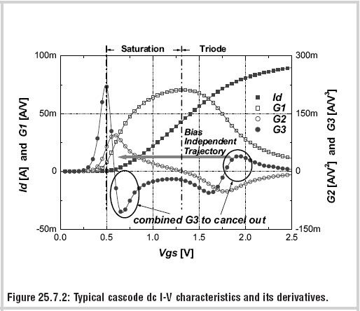
In DC simulation, we can sweep the bias voltage (Vbias), and we can plot the dc I-V characteristics, and gm and gm'... over the large range of sweeping voltage (Vbias).


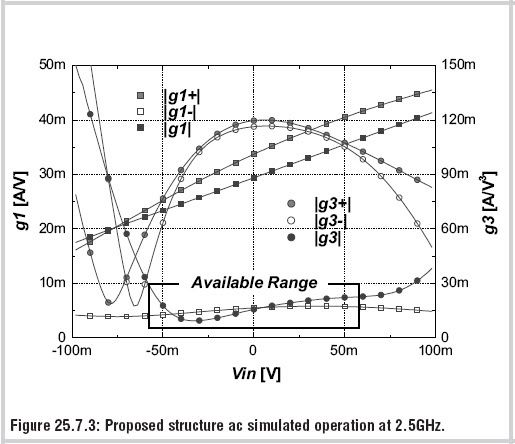
In "A 2GHz 16dBm IIP3 Low Noise Amplifier in 0.25μm CMOS Technology" paper the authors mentioned about AC characteristics, they can also plot the gm over input voltage range (it is AC Vinput, not Vbias).


Can anyone show me how to do this simulation to get that AC gm plot? Thank you very much.
You can check the paper out at this
http://ieeexplore.ieee.org/stamp/stamp.jsp?arnumber=01234383


Title: Re: ac gm simulation
Post by pancho_hideboo on Mar 13th, 2009, 8:16am


vivarf wrote on Mar 11th, 2009, 10:56pm:
Can anyone show me how to do this simulation to get that AC gm plot?

Maybe this is a differential input transconductor. Is it correct ?
Apply swept DC values(-100mV ~ +100mV) as Vin_diff and then evaluate Y21 by executing AC analysis(2.5GHz) under each Vin_diff bias points.

g1 is calculated as g1=real(Y21).
g3 is calculated as g3=d2g1/dVin_diff2.

Although I don't see the following, I guess g1=g1+ + g1-. Is this correct ?

vivarf wrote on Mar 11th, 2009, 10:56pm:
http://ieeexplore.ieee.org/stamp/stamp.jsp?arnumber=01234383

Title: Re: ac gm simulation
Post by vivarf on Mar 15th, 2009, 2:28am

Thank you pancho.

I may need to spend some time to carry the simulation as you suggested to confirm.

About the second figure, I also guess g1 = g1+ + (-) g1-,  not sure either  :(


Title: Re: ac gm simulation
Post by vivarf on Mar 17th, 2009, 4:45am

Hello pancho, sorry to bother you again


Quote:
Maybe this is a differential input transconductor. Is it correct ?
Apply swept DC values(-100mV ~ +100mV) as Vin_diff and then evaluate Y21 by executing AC analysis(2.5GHz) under each Vin_diff bias points.


I carried the AC analysis.
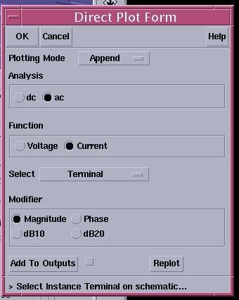
At the result window of AC analysis, as shown below


Quote:

g1 is calculated as g1=real(Y21).
g3 is calculated as g3=d2g1/dVin_diff2.


I supposed Y21 = d[mag(Iout)]/dVin_diff

Is it??

Title: Re: ac gm simulation
Post by pancho_hideboo on Mar 17th, 2009, 6:11am


vivarf wrote on Mar 17th, 2009, 4:45am:
I supposed Y21 = d[mag(Iout)]/dVin_diff
No. You are completely misunderstanding.

Show me your netlist regarding
  signal sources statements
  analysis statements
  options statements
  save statements which you observe output currents.

I will correct your netlist.

And show me your definition of Y21 for differential output current.

I define it as Y21=(Iout+-Iout-)/(Vin+-Vin-).

Also I don't use Direct Plot of Cadence Spectre, since there exist many many unbelievable mistakes in definition.
I use Ocean Script where I write measurement by my own definition.
This is very common in Agilent Tool Environment.

Title: Re: ac gm simulation
Post by vivarf on Mar 17th, 2009, 7:08am

Hi pancho, thank you for your quick response !

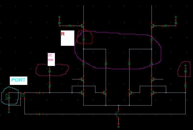
Here my circuit, I just re-build the one that mentioned in the paper.


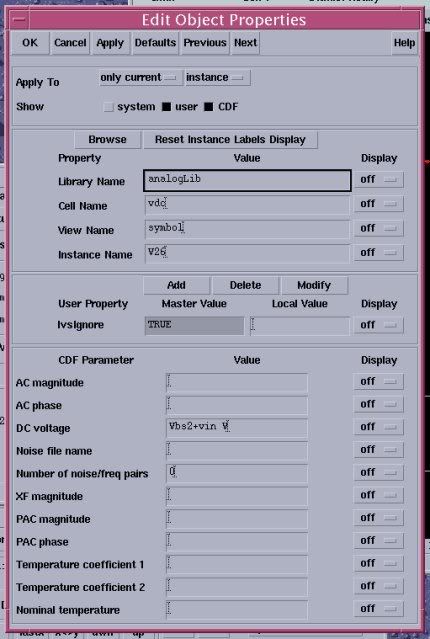
The option of the DC bias , one is Vbs2+vin, the other is Vbs2-vin


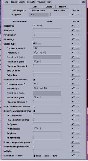
The option of the port (for AC analysis??)


Those resistors are all 0 just to check the current, and after AC analysis I just take out the current of 1 branch of the circuit at terminal of R (first Fig)

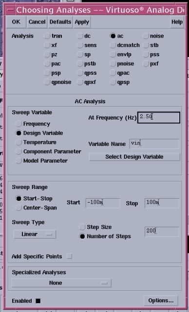
The ac analysis setting


Title: Re: ac gm simulation
Post by pancho_hideboo on Mar 17th, 2009, 7:11am

Show me your netlist regarding
 signal sources statements
 analysis statements
 options statements
 save statements which you observe output currents.

And show me your definition of Y21 for differential output current.

Why do you use port ?
Anyway show me your netlist.

Title: Re: ac gm simulation
Post by vivarf on Mar 17th, 2009, 7:22am

The netlist:

// Generated for: spectre
// Generated on: Mar 17 22:37:31 2009
// Design library name:
// Design cell name:
// Design view name:
simulator lang=spectre
global 0
include "/cadence/IC5141/tools/dfII/samples/artist/ahdlLib/quantity.spectre"
parameters Vbs=.6 Rf_freq=455M Rf_freq2=450M Rf_pwr=-60 vin=0 Vbs2=500m \
   n1=18 n2=18 xxx=8
include "/tsmc13rf/../models/RF_12_33_FSG.scs"


subckt b_wire _1 _2
parameters length
   R0 (net5 _2) resistor r=0.2*length
   L0 (_1 net5) inductor l=0.8n*length
ends b_wire
// End of subcircuit definition.

// Library name:
// Cell name:
// View name: schematic
R28 (net088 net0276 ) rppolyhri l=15.0u w=1u m=1

R6 (net0150 net095 ) rppolyhri l=15.0u w=1u m=1

R2 (net067 net090 ) rppolyhri l=4.05u w=8u m=1

R31 (net069 net068 ) rppolyhri l=15.0u w=1u m=1

R27 (net0276 net093 ) rppolyhri l=15.0u w=1u m=1

R39 (net0162 net072 ) rppolyhri l=15.0u w=1u m=1

R38 (net072 net0274 ) rppolyhri l=15.0u w=1u m=1

R26 (net0274 net076 ) rppolyhri l=15.0u w=1u m=1

R35 (net068 net078 ) rppolyhri l=15.0u w=1u m=1

R36 (net076 net069 ) rppolyhri l=15.0u w=1u m=1

R34 (net078 o\- ) rppolyhri l=15.0u w=1u m=1

R30 (net092 net0275 ) rppolyhri l=15.0u w=1u m=1

R37 (net0275 net0162 ) rppolyhri l=15.0u w=1u m=1

R32 (net089 net088 ) rppolyhri l=15.0u w=1u m=1

R33 (o\+ net089 ) rppolyhri l=15.0u w=1u m=1

R29 (net093 net092 ) rppolyhri l=15.0u w=1u m=1

R45 (net095 net094 ) rppolyhri l=15.0u w=1u m=1

R21 (net097 net0150 ) rppolyhri l=15.0u w=1u m=1

R1 (net099 net0103 ) rppolyhri l=15.0u w=1u m=1

R44 (net0101 net097 ) rppolyhri l=15.0u w=1u m=1

R46 (net0103 net090 ) rppolyhri l=15.0u w=1u m=1

R40 (net066 net0101 ) rppolyhri l=15.0u w=1u m=1

R0 (net0107 net099 ) rppolyhri l=15.0u w=1u m=1

R5 (net094 net0107 ) rppolyhri l=15.0u w=1u m=1

M20 (cmfb cmfb net066 net066) pmos_rf lr=130.0n wr=2u nr=8 m=1
M13 (bias1 net0116 net066 net066) pmos_rf lr=350.0n wr=2u nr=2 m=1
M9 (o\- cmfb net066 net066) pmos_rf lr=130.0n wr=4u nr=64 m=2
M50 (o\+ cmfb net066 net066) pmos_rf lr=130.0n wr=4u nr=64 m=2
M21 (net0160 net0160 net066 net066) pmos_rf lr=130.0n wr=2u nr=8 m=1
M14 (net0116 net0116 net066 net066) pmos_rf lr=350.0n wr=2u nr=2 m=1
I298 (0 net090) b_wire length=2
I296 (0 net062) b_wire length=2
K0 (net0112 0 net215 net025) transformer
C2 (net025 in\-) capacitor c=10p
C1 (net215 in\+) capacitor c=10p
M11 (net0116 bias1 net067 net067) nmos_rf lr=350.0n wr=2u nr=1 m=1
M19 (cmfb net0150 net0156 net0156) nmos_rf lr=130.0n wr=2u nr=4 m=1
M16 (net0156 bias1 net090 net090) nmos_rf lr=350.0n wr=2u nr=4 m=1
M17 (net0156 bias1 net090 net090) nmos_rf lr=350.0n wr=2u nr=4 m=1
M18 (net0160 net0162 net0156 net0156) nmos_rf lr=130.0n wr=2u nr=4 m=1
M15 (net0116 net0116 bias1 bias1) nmos_rf lr=130.0n wr=2u nr=16 m=1
M12 (bias1 bias1 net090 net090) nmos_rf lr=350.0n wr=2u nr=1 m=1
M64 (net018 in\- net043 net043) nmos_rf lr=130.0n wr=2u nr=xxx m=1
M6 (o\- net0132 net074 net074) nmos_rf lr=130.0n wr=2u nr=n1+n2 m=1
M68 (net043 in\+ net062 net062) nmos_rf lr=130.0n wr=2u nr=n2 m=1
M5 (net036 in\- net062 net062) nmos_rf lr=130.0n wr=4u nr=n1 m=1
M3 (net044 in\+ net040 net040) nmos_rf lr=130.0n wr=2u nr=xxx m=1
M4 (net040 in\- net062 net062) nmos_rf lr=130.0n wr=2u nr=n2 m=1
M0 (net014 in\+ net062 net062) nmos_rf lr=130.0n wr=4u nr=n1 m=1
M2 (o\+ net021 net084 net084) nmos_rf lr=130.0n wr=2u nr=n1+n2 m=1
R17 (net0132 net064) resistor r=10K
R7 (net014 net048) resistor r=0
R14 (in\- net070) resistor r=10K
R15 (net044 net096) resistor r=0
R12 (net036 net096) resistor r=0
R19 (net096 net074) resistor r=0
R3 (in\+ net042) resistor r=10K
R4 (net018 net048) resistor r=0
R18 (net048 net084) resistor r=0
R10 (net021 net050) resistor r=10K
V39 (net066 0) vsource dc=1.2 type=dc
V37 (net070 0) vsource dc=Vbs2-vin type=dc
V38 (net064 0) vsource dc=1 type=dc
V26 (net042 0) vsource dc=Vbs2+vin type=dc
V35 (net050 0) vsource dc=1 type=dc
PORT0 (net0112 0) port r=50 num=1 type=sine freq=Rf_freq dbm=Rf_pwr \
       freq2=Rf_freq2 dbm2=Rf_pwr mag=100m fundname="Rf1" fundname2="Rf2"
simulatorOptions options reltol=1e-3 vabstol=1e-6 iabstol=1e-12 temp=27.0 \
   tnom=27 scalem=1.0 scale=1.0 gmin=1e-12 rforce=1 maxnotes=5 maxwarns=5 \
   digits=5 cols=80 pivrel=1e-3 sensfile="../psf/sens.output" \
   checklimitdest=psf
dcOp dc write="spectre.dc" maxiters=150 maxsteps=10000 annotate=status
dcOpInfo info what=oppoint where=rawfile
dc dc param=vin start=-450m stop=2 lin=200 oppoint=rawfile maxiters=150 \
   maxsteps=10000 annotate=status
ac ac freq=400M param=vin start=-100m stop=100m lin=200 annotate=status
tran tran stop=50n step=10p maxstep=40p write="spectre.ic" \
   writefinal="spectre.fc" annotate=status maxiters=5
finalTimeOP info what=oppoint where=rawfile
modelParameter info what=models where=rawfile
element info what=inst where=rawfile
outputParameter info what=output where=rawfile
designParamVals info what=parameters where=rawfile
primitives info what=primitives where=rawfile
subckts info what=subckts  where=rawfile
saveOptions options save=all pwr=all currents=all useprobes=yes \
   saveahdlvars=all

I just check single branch output, because in the paper, I think they use single-ended. And the expression of Y21:

Y21=deriv(i("/R18/MINUS" ?result "ac"))

Title: Re: ac gm simulation
Post by pancho_hideboo on Mar 17th, 2009, 8:36am

I don't need full netlist.
Read my requests surely.

You should not use Resistor of 0ohm for observing current.
Instead use vsource of dc=0Volt or iprobe.

Your netlist is too dirty and wrong, so it is laborious to correct.


vivarf wrote on Mar 17th, 2009, 7:22am:
PORT0 (net0112 0) port r=50 num=1 type=sine freq=Rf_freq dbm=Rf_pwr \
      freq2=Rf_freq2 dbm2=Rf_pwr mag=100m fundname="Rf1" fundname2="Rf2"
K0 (net0112 0 net215 net025) transformer
C2 (net025 in\-) capacitor c=10p
C1 (net215 in\+) capacitor c=10p

R3 (in\+ net042) resistor r=10K
V26 (net042 0) vsource dc=Vbs2+vin type=dc

R14 (in\- net070) resistor r=10K
V37 (net070 0) vsource dc=Vbs2-vin type=dc

tran tran stop=50n step=10p maxstep=40p write="spectre.ic" \
  writefinal="spectre.fc" annotate=status maxiters=5
finalTimeOP info what=oppoint where=rawfile
Delete these lines completely. And replace to the followings.

V26 (in\+ 0) vsource type=dc dc=Vbs2+vin/2 mag=0.5 phase=0
V37 (in\- 0) vsource type=dc dc=Vbs2-vin/2 mag=0.5 phase=180


vivarf wrote on Mar 17th, 2009, 7:22am:
ac ac freq=400M param=vin start=-100m stop=100m lin=200 annotate=status
Modify this line to the following.

ac ac freq=400M param=vin start=-100m stop=100m lin=200 annotate=status restart=yes


vivarf wrote on Mar 17th, 2009, 7:22am:
Y21=deriv(i("/R18/MINUS" ?result "ac"))
You are misunderstanding completely.

Y21=i("/M2/D" ?result "ac")-i("/M6/D" ?result "ac")
g1=real(Y21), g3=deriv( deriv(g1) )

If you prefer single-ended output, Y21=i("/M2/D" ?result "ac").

I can't find out output terminals for g1+ and g1- correctly.
If you specify output terminals correctly for them, you can calculate g1+ and g1- by same definition as g1.

I've been very tired due to your unbelievable misunderstanding netlist.

Title: Re: ac gm simulation
Post by vivarf on Mar 17th, 2009, 8:54am

My mistake, because I hardly use the script, so netlist is not familiar with me

Pancho, thank you very much, I really appreciate.

Title: Re: ac gm simulation
Post by Ken Kundert on Mar 17th, 2009, 9:36am

In Spectre there is nothing wrong with using a zero ohm resistor to measure current, just like it is fine to use a zero volt voltage source. Using the iprobe is actually preferred because it is a very simple and light weight component.

-Ken

Title: Re: ac gm simulation
Post by pancho_hideboo on Mar 17th, 2009, 9:55am


Ken Kundert wrote on Mar 17th, 2009, 9:36am:
In Spectre there is nothing wrong with using a zero ohm resistor to measure current, just like it is fine to use a zero volt voltage source.

I feel it comes to be slow if I use resistor of 0ohm instead of vsource of 0Volt when I run HB analysis of Cadence Spectre.

Title: Re: ac gm simulation
Post by pancho_hideboo on Mar 17th, 2009, 7:17pm


vivarf wrote on Mar 17th, 2009, 8:54am:
My mistake, because I hardly use the script, so netlist is not familiar with me
Pancho, thank you very much, I really appreciate.
Can you understand what is your misunderstanding ?

Title: Re: ac gm simulation
Post by wave on Mar 17th, 2009, 7:36pm


Ken Kundert wrote on Mar 17th, 2009, 9:36am:
In Spectre there is nothing wrong with using a zero ohm resistor to measure current, just like it is fine to use a zero volt voltage source. Using the iprobe is actually preferred because it is a very simple and light weight component.

-Ken


Ken - When I use tiny R's, I find abstol, reltol type of issues.
Usually atleast 100 mOhms is a good compromise.

Vdc=0 works well for me, as it back annotates well.  

I've never understood why iprobe exists.  
Doesn't back annotate that well.

Oddly, the STB analysis can use either device, and I'm curious if there is a tradeoff.
Usually I swap out my STB symbol for Metal R's, so it's always good to have a value that converges 8-)

~Wave


Title: Re: ac gm simulation
Post by vivarf on Mar 17th, 2009, 8:36pm


Quote:
Can you understand what is your misunderstanding ?


I am still a little confused here

The original definition: Y21=Id/Vin

The result you defined is taken out current: Y21=i("/M2/D" ?result "ac")   (single-ended)

From the original definition, I thought Y21 = deriv(i("/M2/D" ?result "ac"))

Title: Re: ac gm simulation
Post by pancho_hideboo on Mar 17th, 2009, 8:54pm

Do you have basic knowledge of RF circuit  theory although "RF" is included in your name "vivarf" ?
Maybe you are "unvivarf".

You should learn small signal analysis with a starter of the following post.
http://www.designers-guide.org/Forum/YaBB.pl?num=1236321645


vivarf wrote on Mar 17th, 2009, 8:36pm:
The original definition: Y21=Id/Vin
Here Id and Vin are both small signal value in AC Analysis.


vivarf wrote on Mar 17th, 2009, 8:36pm:
The result you defined is taken out current: Y21=i("/M2/D" ?result "ac")   (single-ended)
This is because I set Vin as 1.0V in AC analysis.

You might think calculation of g2 and g3 is irregular since it uses both DC analysis result and AC analysis result.
But it is matched to an actual measurements using actual instruments.

S-parameters are measured by Vector Network Analyzer(SP-Analysis) with sweeping DC bias points feeded via Bias-Tee.
Y21 is evaluated from S-parameters. g2 and g3 are calculated by derivation of g1=real(Y21) regarding DC bias points difference.

I always say to people in this Forum, "You have to learn measurements using actual instruments". Not "EDA Tool Play".


vivarf wrote on Mar 17th, 2009, 8:36pm:
From the original definition, I thought Y21 = deriv(i("/M2/D" ?result "ac"))
No. You are still misunderstanding the original definition.
You can't understand gm in DC Analysis and Y21 in AC analysis.
First of all, you can't understand small signal analysis such as AC, XF, SP Analysis at all.
Learn Y,Z,S-Prameters of linear system.

Maybe you are student. So discuss such too basic issues with friends.

Title: Re: ac gm simulation
Post by vivarf on Mar 17th, 2009, 11:22pm


Quote:
This is because I set Vin as 1.0V in AC analysis.


Now I got it (at least in this situation).


Quote:
No. You are still misunderstanding the original definition.
You can't understand gm in DC Analysis and Y21 in AC analysis. First of all, you can't understand small signal analysis such as AC, XF, SP Analysis at all.
Learn Y,Z,S-Prameters of linear system.

Maybe you are student. So discuss such too basic issues with friends.


You were right, I should have learnt those more carefully.

Thank you pancho.

Title: Re: ac gm simulation
Post by Andrew Beckett on Mar 20th, 2009, 2:19pm


wave wrote on Mar 17th, 2009, 7:36pm:

Ken Kundert wrote on Mar 17th, 2009, 9:36am:
In Spectre there is nothing wrong with using a zero ohm resistor to measure current, just like it is fine to use a zero volt voltage source. Using the iprobe is actually preferred because it is a very simple and light weight component.

-Ken


Ken - When I use tiny R's, I find abstol, reltol type of issues.
Usually atleast 100 mOhms is a good compromise.


Actually Ken talked about a 0 ohm resistor, not a tiny value resistor. Tiny value resistors can indeed cause convergence difficulties, but 0 ohm should be fine.

Hopefully my response is a little more polite than some of the responses in this thread  ;)

Regards,

Andrew.

Title: Re: ac gm simulation
Post by pancho_hideboo on Mar 22nd, 2009, 8:52pm


Andrew Beckett wrote on Mar 20th, 2009, 2:19pm:
Hopefully my response is a little more polite than some of the responses in this thread  ;)
I'm always very honest. :D

Attached figure is comparison using two tones HB-QPSS of Cadence Spectre.
Apparently resistor of 0ohm cosumes much memory and it's speed is slow compared to vsource of vdc=0V.

I always feel that simulation speed is slow and memory consumption is large if I use iterative instances which include resistor of 0ohm instead of vsource of vdc=0V.


Title: Re: ac gm simulation
Post by Andrew Beckett on Mar 22nd, 2009, 10:53pm

I didn't say that a zero-ohm resistor was completely free; you'd be better off with an iprobe (even that isn't completely free if you have many of them). If you've only got a single resistor/vsource/iprobe it's not going to make significant difference - my point was rather that using a small value resistor can cause convergence difficulties, whereas 0ohms should be OK.

I wasn't doubting the honesty of your reply (honest!)

Regards,

Andrew.

Title: Re: ac gm simulation
Post by Ken Kundert on Mar 23rd, 2009, 11:29pm

I have to differ with both of you. First, on the zero ohm resistors, from a simulation perspective, they are structurally identical to 0-volt voltage sources. In fact, they tend to have a smaller memory footprint, and so if anything they should be faster. Unless there is a bug in the simulator, which is hard to imagine because they are so simple and heavily used, it is very unlikely that there is a significant speed difference between the two.

Concerning your results, I would council you not to put too much stock in such small differences. I have looked at a very large number of simulation speed issues through the years and have found that they are often due to happenstance.

Second, on convergence problems with small resistors, this would only be true with small parasitic resistors. This is one reason why they are automatically deleted. However, normal resistors have a more sophisticated formulation that allows them to work with any resistance, no matter how large or how small. The only reason why you would have trouble is if the thresh parameter was set incorrectly, which again occurs only very rarely, and when it does occur it is often the result of overly aggressive tightening of tolerances, particular abstol.

Finally, concerning your honesty Pancho, I cannot know what you really believe. However I have always found your opinions about Spectre and SpectreRF to be excessively negative, and frankly far outside outside the mainstream. You and I both know that you have very personal reasons to dislike Cadence, and I think you are letting your feelings about Cadence affect what you say about Spectre. In addition, I often find your manner on this forum to be overly harsh, and occasionally insulting. However, at the same time you are very helpful to the people on this forum. You are very active, and very knowledgeable, and on the whole I value your contribution. Perhaps you can try to be a little more even handed in your treatment of Spectre and a little more gentle in your treatment of the other members of the forum. After all, we are all friends here just trying to help each other out.

-Ken


The Designer's Guide Community Forum » Powered by YaBB 2.2.2!
YaBB © 2000-2008. All Rights Reserved.