Post by baab on Feb 18th, 2014, 2:26am
Hi,
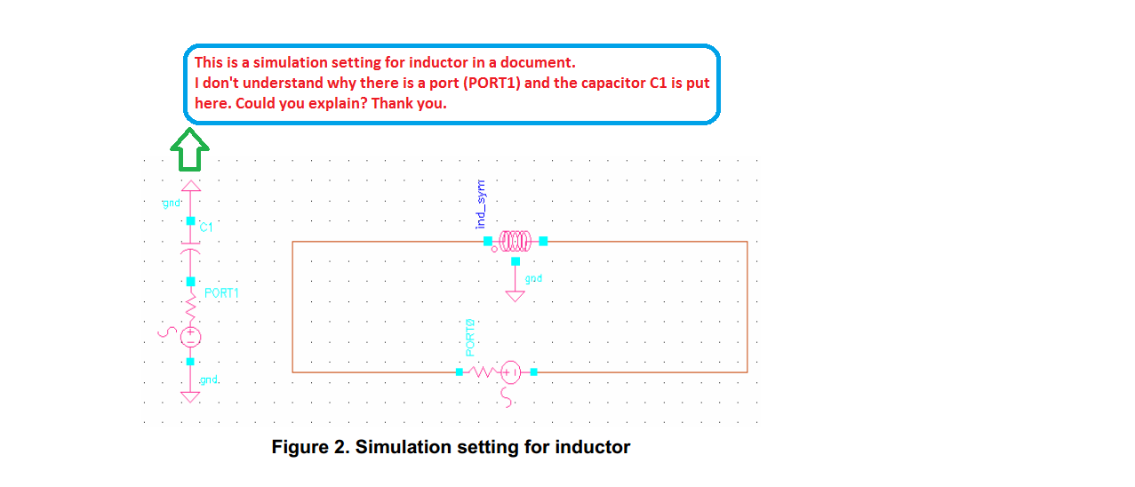
Please help me with the question in the picture? Thanks.
|
The Designer's Guide Community Forum
https://designers-guide.org/forum/YaBB.pl Simulators >> Circuit Simulators >> Confusion about simulation settting for inductor https://designers-guide.org/forum/YaBB.pl?num=1392719194 Message started by baab on Feb 18th, 2014, 2:26am |
|
Title: Confusion about simulation settting for inductor Post by baab on Feb 18th, 2014, 2:26am Hi, Please help me with the question in the picture? Thanks.
|
|
Title: Re: Confusion about simulation settting for inductor Post by Andrew Beckett on Feb 18th, 2014, 4:28pm A wild guess is that this is some setup to do an s-parameter simulation of both a capacitor and an inductor. Without knowing the source of the picture I doubt anyone can help very much... Andrew. |
|
Title: Re: Confusion about simulation settting for inductor Post by baab on Feb 18th, 2014, 11:23pm Thank you, Andrew. It is from a document guiding to simulate VCO. And you are right; the set up is used to simulate Z-parameters and Quality factor Q for both capacitor and inductor. However, they are done seperately. If we only want to know Z-parameters and Quality factor Q for an inductor, I see there is no need to use PORT1 and C1 here. Could you explain a bit more about this type of setting? |
|
Title: Re: Confusion about simulation settting for inductor Post by Andrew Beckett on Feb 19th, 2014, 12:21am What kind of "setting"? There's no "setting" here... If using s-parameter analysis, you have to have ports - the simulator analyses the s-parameter matrix between the ports (in this case the only useful information would be S11 and S22 which would be single-ended s-parameters for the capacitor and inductor - none of the other matrix elements would be useful because there's no coupling between the ports. Regards, Andrew. |
|
Title: Re: Confusion about simulation settting for inductor Post by baab on Feb 19th, 2014, 6:06pm Thank you. I will upload that file when I get home. It is written in Korean and I couldn't understand it well. |
|
Title: Re: Confusion about simulation settting for inductor Post by aaron_do on Feb 19th, 2014, 8:59pm Hi baab, there should be plenty of references around for how to model an inductor. Why did you choose one in Korean? Anyway the procedure is very straightforward and logical. You just need to first be able to visualize what kind of passive components the structure will have. For example, a long straight line over a grounded substrate can be modeled as a series R+L with capacitors distributed along the R and L. This can be simplified as an R+L with a shunt cap at either end. After you have drawn your model, you need to find the component values. This is quite easy to do if you understand Y and Z parameters. If you want to make your model more complex, you can then start talking about magnetic coupling, and the skin effect etc... regards, Aaron |
|
Title: Re: Confusion about simulation settting for inductor Post by tuza2000 on Jul 20th, 2015, 10:07pm baab wrote on Feb 19th, 2014, 6:06pm:
can you share the reference document?thanks! |
|
Title: Re: Confusion about simulation settting for inductor Post by tuza2000 on Jul 20th, 2015, 10:34pm Andrew Beckett wrote on Feb 19th, 2014, 12:21am:
what's the scheme for simulate the quality factor of Parallel LC resonator? just simulate the seperate quality and using the formular of Qtank=Qc*Ql/(Qc+Ql) ? |
|
The Designer's Guide Community Forum » Powered by YaBB 2.2.2! YaBB © 2000-2008. All Rights Reserved. |