The Designer's Guide Community
Forum
Welcome, Guest. Please Login or Register. Please follow the Forum guidelines.
Jul 28th, 2024, 5:20am
Pages: 1
Send Topic Print
Driven Right Leg circuit (Read 6459 times)
Victor chan
New Member
*
Offline


Posts: 5

Driven Right Leg circuit
Dec 28th, 2010, 4:51am
 
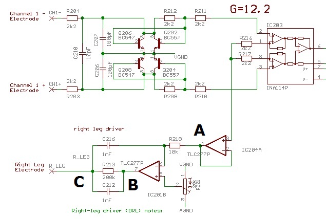
Here is a picture of a part of a circuit, which contains a right leg driver.

My understanding of DRL is a circuit which send a signal to a human body, therefore this human body would have the same 'common voltage' as the circuit, which helps to increase CMRR.

However, I would like to know how the below DRL works, especially at the point A, B and C.

Also I have seen quite a few of DRL circuits, and they all do some sort of filtering (Low pass filter), I would like to know what value of cut off freq is aiming actually.

Back to top
 
 
View Profile   IP Logged
philcorb
Junior Member
**
Offline


Posts: 17

Re: Driven Right Leg circuit
Reply #1 - Feb 18th, 2011, 6:49am
 
Hi,

The DRL circuit essentially places the human body within the a common-mode feedback loop, mainly to minimise 50/60Hz main-hum picked up by the body.  The low-pass filtering is for loop stability.

Hope this helps
Back to top
 
 
View Profile   IP Logged
Pages: 1
Send Topic Print
Copyright 2002-2024 Designer’s Guide Consulting, Inc. Designer’s Guide® is a registered trademark of Designer’s Guide Consulting, Inc. All rights reserved. Send comments or questions to editor@designers-guide.org. Consider submitting a paper or model.