Hi all,
i'm trying to simulate the output impedance of an NMOS transistor at 2.45 GHz. The DC solution in theory is roughly,
Rout = 1/lambda.IDS
my setup is like this,
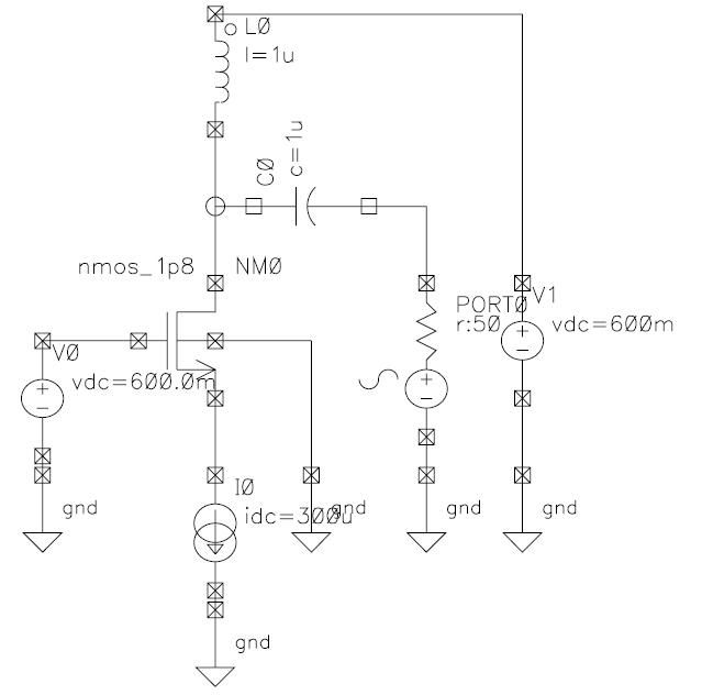
As you can see, the current is fixed by the ideal current source at the source of the transistor. I used S-Parameter analysis and plotted Z11 in magnitude. Thus is contains both the real and imaginary component. I am using the 0.18 um process and the PDK i'm using has so far proven to be reliable enough.
Sweep Dependence
------- --------------
VGS weak
IDC weak
VDD weak
L quite weak
Fingers weak*
W Strong
So from the data i found that by far the biggest factor in determining the output impedance was the transistor width. Is this a well known phenomenon? I thought that at 2.45 GHz the transistor would still roughly follow the DC solution.
The strange thing is that when i ran a simulation of output impedance versus IDC for a full LNA, I found it to roughly follow the 1/IDC curve. So anybody know what i've been doing wrong or what's going on?
thanks,
Aaron


 Home
Home
 Pages: 1


 RF NMOS output impedance (Read 6264 times)